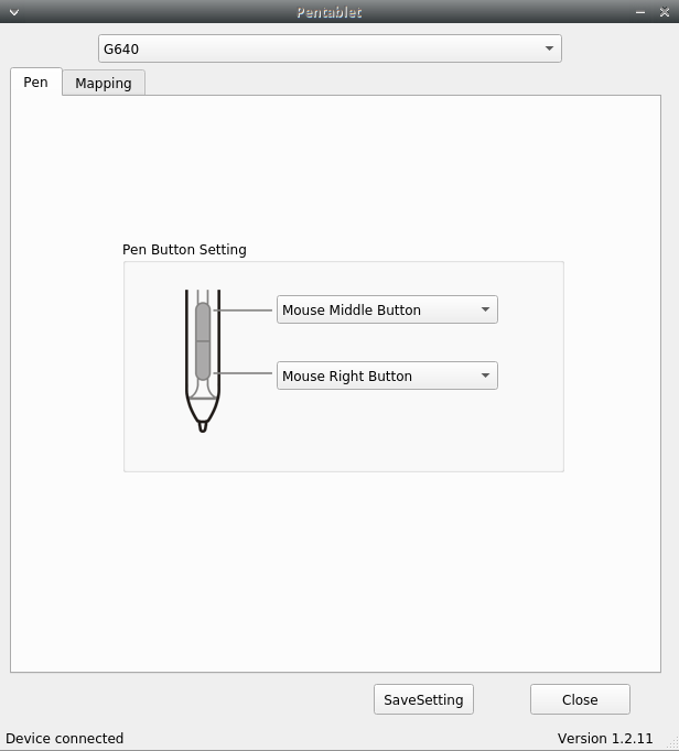
When you plug in your Xp-pen graphic tablet into your Linux machine (i am running xubuntu-18.04), you will notice that the XP-Pen that you are using will be detected in the ‘Mouse and Touchpad’ settings tab:
But the pen may not work! Although the device is enabled, writing on the drawing tablet using the pen does not have any effect. If you stumble upon this problem then there is a fairly simple solution that will resolve this issue: Solution:
(ii) Unzip all the contents of the downloaded Linux Beta driver from xp-pen’s website into ‘/home/User/Linux/’ directory
Here’s what my Linux directory looked like :
(iii) Make Pentable_driver.sh as executable
cd /home/User/Linux
chmod +x Pentablet_Driver.sh
(iv) Connect your device and run Pentablet_Driver.sh
(sudo) ./Pentablet_Driver.sh
The above screen should pop up and your device should work ! Open gimp to test it out.
** I had to make a dedicated directory titled Linux and place it under the home directory for this to work. Else I constantly run into issues loading the xp-pen’s library files. I tested on two Xubuntu machines and both had the same issue. But this may not been a necessary step for other distros.
Key Insight: We took the output of the drawdio circuit and connected it to the mic pin of the headphone jack like so :
This was our key breakthrough. Having interfaced the drawdio with the computer opened a plethora of possibilities for us to play around with.
In this following videos, we have connected the pin -3 of the drawdio circuit (above) to the mic of the headphone jack and in the placeholder of R5, we insert different sensors such as the LDR(Light dependent Resistor). IR led, etc. This allows us to have an audible feedback from the sensors that are connected, making them ‘come alive’.
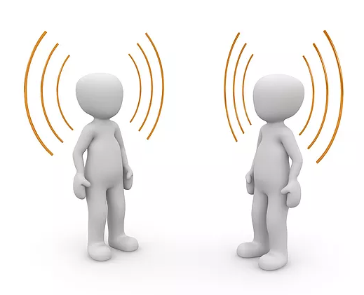
Humans as antennas is an established paradigm and the works on Body Coupled Communications(BCC) and Personal Area Netwok (PAN) from the MIT media lab are at the frontiers of innovation based on this concept. Their works get into the technicalities of such a communication such as protocols, circuit design, etc. The only down side being that, the technology is inaccessible to the common man. If you still want to experiment with it, we have something that could get you started.
In this post, we connected the headphone jack’s mic wire to the human body and used it to transmit and receive signals through space – Wireless!
Why the headphone jack ? Why not? Not only is it something that is readily accessible, it also does not require additional hardware.
Demonstration:
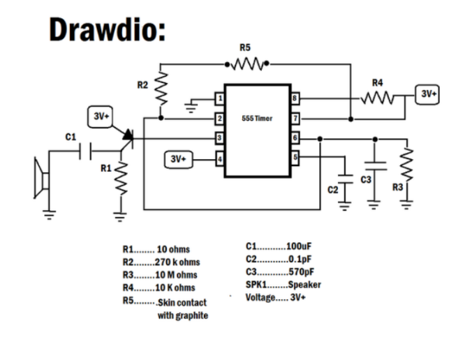
In this post, we demonstrate this idea by turning the drawdio circuit made by Jay Silver using the 555 timer ‘wireless’ by using the human as an antenna.
In order to make the drawdio circuit (see diagram below) wireless, take out R5 and place your hand instead to complete the circuit.
Hook up a headphone jack to your computer and listen to the signals received on your mic. Your body will act as an antenna and you will be able to receive the signal on your computer. Make sure to adjust the gain of the microphone accordingly.
Now if you are aware about common grounds then the above video might not seem as appealing because the drawdio in the above case by powered by an Arduino connected to the computer which is receiving the audio signal. The same concept does work with different grounds as well as we demonstrate in the following video where the drawdio is powered externally through an OTG cable.
If you would like to transmit the drawdio output in the RF range instead, one can hook up the output of the drawdio to a crystal oscillator and touch the output wire of the crystal oscillator instead. In this video, a 32 MHz crystal oscillator is used and a FM radio app tuned at 96MHz is used to pick up the drawdio signal. This would be another way to demonstrate the idea of using the human body as an antenna.*
Instead of the drawdio, if you would like to transmit serial data from the USB port wireless, we can play the same game. Just place your hand on the TX pin of the USB-TTL and listen on the mic of the headphone.
What can you do with this ?
There are obvious limitations of using a headphone jack for BCC rather than something more dedicated as explored by the folks at the MIT media lab, this post is an exploration on how one can intuitively achieve this using the headphone jack.
*There is a great chance that many of you might have already tried this out in your car at some point.
** More explorations on the drawdio circuit click here
** More explorations on the headphone jack click here.
Although vibration motors are common in Mobile phones, procuring button sized vibration motors were the ultimate challenge. (There were a couple of good ones on ebay, but couldn’t find one at this point of time)
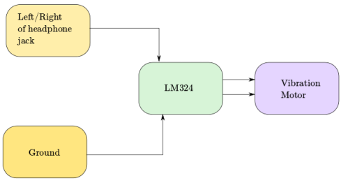
But once that was resolved, one of the leads of the vibration motor was connected to the headphone jack and the ground of the headphone jack to the other lead.
Now square wave signals are played through the headphone jack using Audacity. Although one can feel the motors vibrating, using an operational amplifier such as LM324 helps to intensify the vibrations. ( Power source to LM324 – Battery/Arduino )
Note:
One of the weirdest but yet satisfying experience with the vibration motor is when you connect the vibration motor through the audio jack without any amplifier. You can hear the music being played through the vibration motor. The motors seems to be dancing to the music being played. We tried so hard to capture the phenomenon but the sound was too feeble to be picked up. That shouldn’t stop you from giving it a shot.
Most of us live under the simple algorithm : Plug a headphone into the jack and move on with life. But the beauty of it is what happens during those instances when you insert the jack and the mobile/laptop recognizes the device to be indeed a headphone jack.
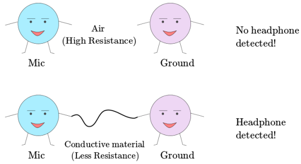
Most modern smart-phones and laptops detect a headphone using the following simple principle :
Establish a potential difference between the mic and the ground ( ~ 2- 3 V ) and observe the resistance. If its high, its air and probably nothing has been inserted. If its really low, then a headphone jack has been inserted.
And the fact that a potential difference is constantly being given between the mic and the ground allows us to plug in a led and light it up .
Corollary 😉 :
All that the phone is looking for low resistance value. You can very easily fool the phone to think that an aluminum foil is a headphone jack.
Older headphone jacks
This answer by Rick on stackexchange answers this question so accurately :
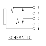
” Headphone jacks have extra contacts inside, which act as switches. The the drawing below, pins 4 and 5 are intended for sensing that the plug was inserted. They are not intended for audio signal. When the plug is not present, the switche, which are formed by 2 & 4 and 3 & 5, are closed.
When the plug is inserted, these switches are open. The plug flexes 2 and 3 slightly, and they break contact with 4 and 5. You could insert a 3.5mm plastic rod [a dummy] into the jack, which will open the contacts, and the phone might think that earphones are plugged in. ”
Headphone jack plugged in or not ? (Software end)
In a previous post , we talked in depth about the /dev/input directory in Linux. This video talks about how the computer knows whether a headphone jack has been plugged in or not from a software point of view.
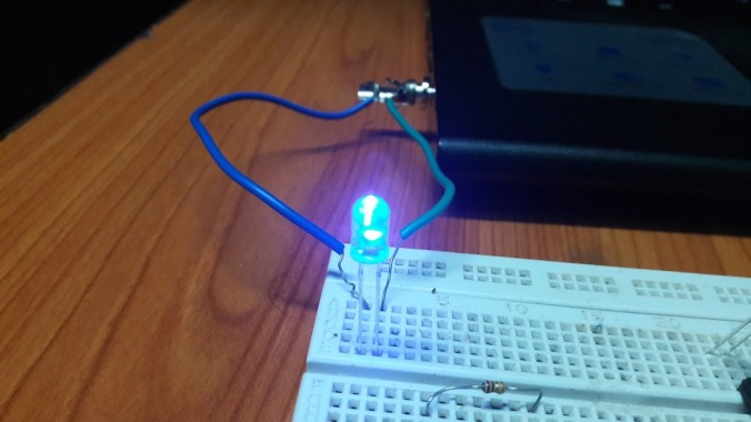
Lighting up an LED using the headphone jack is probably one of most easiest tasks. Take the mic of the TRRS pin ( or left in a TRS ) and connect it to the shorter end of the LED. Take the ground and connect it to the longer end of the led and you are good to go !
A potential difference of ~3V exists between the two pins that is sufficient to light up a LED. Why is there a potential difference in the first place ? Well, this will answered in great detail in one of our post on the Anatomy of a headphone jack.
Now no one wants to stop with just lightning up a LED, so let’s improvise..
Controlling LED brightness
Like we said: A potential difference of ~3V exists between the two pins that is sufficient to light up a LED. By controlling the volume, we can reduce this potential difference and thereby dim the LED.
You can control 2 LEDs (min.) with a single headphone jack
With a simple headphone jack, one is capable of controlling 2 LEDs at the very minimum. Take 2 LEDs and connect them both to the Left/Right in the configuration shown below:
If one plays a square wave through the Left/Right then the first LED would light during the positive half of the cycle and the second one during the negative half. This is because LEDs are conductive only in one direction.
You can watch a demonstration of this in the following video.
And as a bonus, we did a frequency sweep from 1 – 30 Hz (Square Wave) and here is how that looks:
Hang on a second!
If you can do that, then you play songs and also visually witness Beats phenomenon right? Absolutely!
Visualizing songs using LED
Beats phenomenon
Headphone jack as a switch
In all our above setups, we connected the jack directly to the LED. But one might need the LED to be brighter. So, to do that we had to bring in a operational amplifier ( LM324 ). This can be powered using a OTG (On-the-go) cable or using an Arduino.
Now using this we can use the headphone to perform switching operations. And this is what we demonstrate in the following series of videos:
Schematics/Circuit diagrams will be uploaded soon! Thank you.
Sometime ago there was a post on reddit which claimed that you can use your LED as a light sensor to detect the intensity of light. We decided to try it out and oh boy! it completely changed our perspective on the LED.
We just took a LED and performed an AnalogRead on the Arduino. Check this out:

 (i) Make a dedicated directory *: